
Many of the decisions behind embodied carbon in concrete are made during design: how the structure is modeled, how large each element is, what strength the mix requires, and how much reinforcing steel is specified. When these decisions are optimized, cost, carbon, and construction effort drop together.
This article examines two case studies at different scales. The first is a retaining wall I reworked from a design example under review by Committee 332, Residential Concrete, of the American Concrete Institute (ACI). With the same design criteria, the reworked wall uses 33% less concrete and 9% less reinforcing steel. The second is a two story insulated concrete form (ICF) fire rebuild in Altadena, CA. On this project, a low carbon 3,000 psi mix and fiber reinforcement avoided approximately 110,094 pounds of CO₂ equivalent.
The principle is the same at both scales: design each element for the structural demand.
Retaining Wall Case Study
Conventional retaining walls can require extensive reinforcement detailing and associated field labor to cut, bend, place, and tie reinforcing steel. This case study shows how refining the structural analysis, dimensions, and reinforcement can reduce material use, embodied carbon, and construction effort while meeting structural requirements.
As part of my work with ACI Committee 332, Residential Concrete, I reviewed a retaining wall design example and the supporting calculations for inclusion in a guide document. With the same design criteria, I evaluated how the structural model, dimensions, concrete strength, and reinforcement could be optimized while still meeting the structural requirements.
The original design included an approximately 5.5 ft wide footing, driven primarily by an assumed Class 5, low strength soil. The model accounted for active soil pressure against the back of the wall and resistance from the weight of the stem, footing, and soil over the heel.
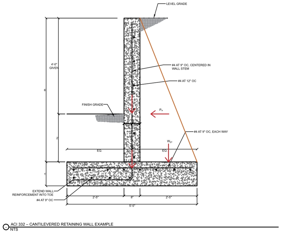
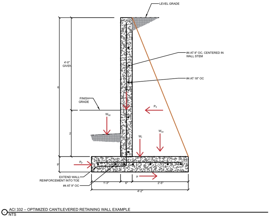
I refined the model to account for additional resistance available within the system: passive soil resistance at the toe, friction along the base of the footing, and the additional soil weight over the toe. A simplified engineering model can sometimes produce a more conservative design. Accounting for additional resisting forces allows a reduction in footing width, footing thickness, and stem thickness while satisfying structural requirements.
| Design Element | Reference Retaining Wall | Optimized Retaining Wall |
|---|---|---|
| Concrete Strength, f’c | 3,000 psi | 2,500 psi |
| Reinforcing Steel, fy | 60 ksi | 40 ksi |
| Stem Height | 6′-0″ | 6′-3″ |
| Stem Thickness | 8″ | 6″ |
| Footing Width | 5.5 ft | 4.25 ft |
| Footing Thickness | 12″ | 9″ |
| Stem Vertical Reinforcement | #4 at 9″ oc | #4 at 8″ oc |
| Stem Horizontal Reinforcement | #4 at 12″ oc | #4 at 18″ oc |
| Toe Reinforcement | #4 at 9″ oc | #4 at 8″ oc |
| Heel Reinforcement | #4 at 9″ oc | #4 at 9″ oc |
| Concrete Volume | 9.42 ft3/LF | 6.31 ft3/LF |
| Reinforcing | 21.23 LF/LF wall | 19.42 LF/LF wall |
| Optimization | Reference | Optimized | Result |
|---|---|---|---|
| Concrete Volume | 9.42 ft3/LF | 6.31 ft3/LF | ↓ 33% |
| Reinforcing Quantity | 21.23 LF/LF | 19.42 LF/LF | ↓ 9% |
| Concrete Strength | 3,000 psi | 2,500 psi | Meets Structural Demand |
| Rebar Yield Strength | 60 ksi | 40 ksi | Meets Structural Demand |
The original design included an 8 inch stem with a 5.5 foot wide, 12 inch thick footing. The optimized design reduced the stem to 6 inches and the footing to 4.25 feet wide by 9 inches thick. Reinforcement changed slightly in several locations, and the design used less concrete and less reinforcing steel overall.
Concrete volume decreased from 9.42 to 6.31 cubic feet per linear foot of wall, or approximately 33%. Total reinforcing steel decreased from 21.23 to 19.42 linear feet per linear foot of wall, or approximately 9%. To test the calculation, I also reduced the concrete strength from 3,000 psi to 2,500 psi and the reinforcing steel yield strength from 60 ksi to 40 ksi. The reworked example still met the structural demand.
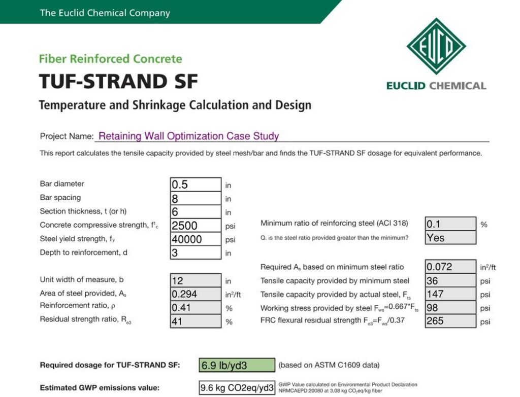
Next, I evaluated fiber reinforced concrete. Using Euclid Chemical’s design tool, I modeled replacing all vertical and horizontal reinforcement in the stem with polypropylene fiber. For the optimized 6 inch stem using 2,500 psi concrete, the calculated dosage was 6.9 pounds of polypropylene fiber per cubic yard of concrete. Fiber substitution must be designed for the specific structural application and code requirements.
When scaled across a 100 foot retaining wall, the reduction in reinforcing steel avoids approximately 502 pounds of CO₂ equivalent. Reducing concrete volume by 33% saves approximately 11.5 cubic yards of concrete and avoids another approximately 5,212 pounds of CO₂ equivalent. Lowering the concrete strength from 3,000 psi to 2,500 psi avoids approximately 1,054 more pounds of CO₂ equivalent.
Combined, the optimizations avoid approximately 6,775 pounds of CO₂ equivalent for every 100 linear feet of retaining wall. A 100 foot retaining wall is not unusual in residential construction, and a retaining wall is only one structural element. Applying the same approach across foundations, walls, slabs, ICF systems, and other concrete elements multiplies reductions across a project.
From a Retaining Wall to an ICF Residence
The retaining wall example demonstrates what optimization can accomplish at the component level. The same principles apply at the building level. In an ICF residence, the wall and foundation systems, concrete mix, reinforcement, detailing, and construction sequence are interconnected. Considering the structural and building envelope systems together creates opportunities to reduce material use, simplify installation, and improve project performance.
The Altadena project shows this approach: coordinated decisions on concrete strength, supplementary cementitious materials (SCMs), volume, reinforcement, and detailing directly influence project cost and embodied carbon.
Altadena Case Study
A custom two story ICF residence in Altadena, California, provides an example at a larger scale. The fire rebuild includes the residence, a detached garage, and an upper story deck. The structure also has structural irregularities: upper story walls offset from lower story walls, and relatively slender ICF wall piers at the lower story.
The ICF walls and foundation at the residence contain approximately 227 cubic yards of concrete. The garage adds another 35 cubic yards, bringing the project total to approximately 263 cubic yards.
The baseline was a 4,000 psi concrete mix. Based on the structural requirements, I designed the concrete for 3,000 psi instead. I worked with Holliday Rock, a supplier serving the project area, to develop a low carbon 3,000 psi mix. Holliday Rock recommended approximately 50% fly ash for the ICF system.
The optimized mix lowered the concrete cost to approximately $150 per cubic yard and the embodied carbon to approximately 407 pounds of CO₂ equivalent per cubic yard. Compared with the baseline 4,000 psi mix, the optimized 3,000 psi mix saves approximately $7,400 in concrete cost. Applied across approximately 263 cubic yards of concrete, the optimized 3,000 psi mix also avoids approximately 106,900 pounds of CO₂ equivalent. The CO₂ savings equal approximately 44,700 passenger vehicle miles, or about 4.1 passenger vehicles driven for one year.
Although the project is in a high seismic region, I incorporated fiber reinforcement to reduce conventional reinforcing steel in the ICF wall system. Approximately 50% of the conventional reinforcement was replaced with Euclid polypropylene fiber while maintaining the required structural performance. I also specified Helix steel fiber in portions of the foundation and slab. These project specific design decisions reduced rebar placement and associated labor, supporting faster, more efficient construction.
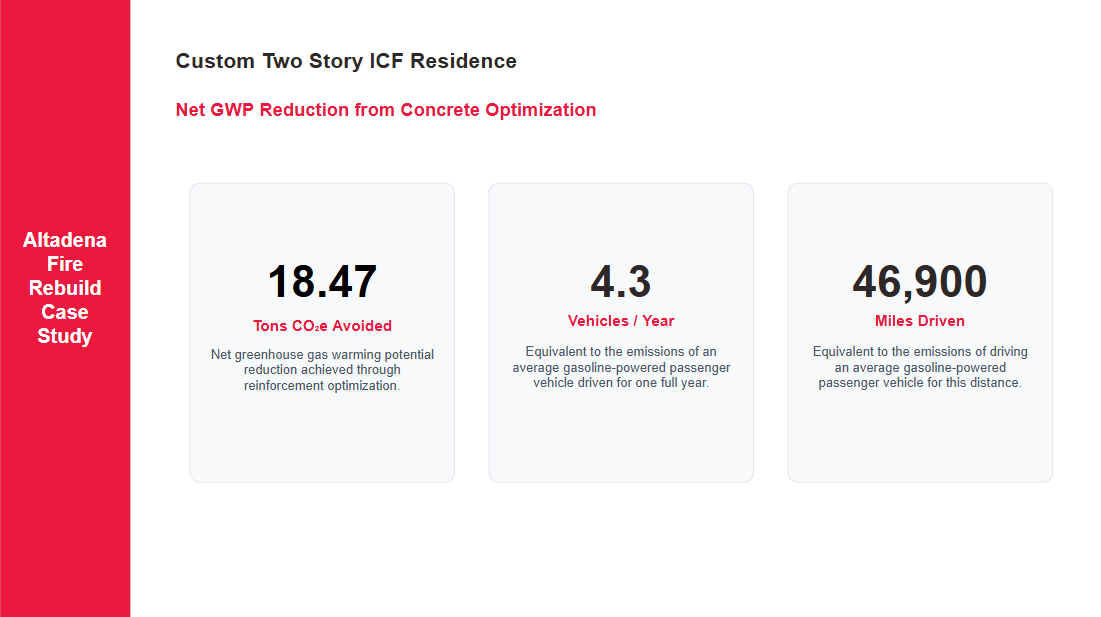
Replacing conventional reinforcing steel with polypropylene fiber avoided an additional 3,194 pounds of CO₂ equivalent, bringing the total project savings to approximately 110,094 pounds of CO₂ equivalent. The total equals approximately 46,900 passenger vehicle miles, or about 4.3 passenger vehicles driven for one year.
An Integrated Approach to Optimization
The retaining wall and Altadena case studies operate at different scales, yet point to the same design principle: optimization is most effective when the structure is treated as an integrated system rather than a series of isolated components. At both component and building levels, opportunities for optimization come from evaluating how structural analysis, concrete strength, mix design with SCMs, reinforcement, detailing, and construction methods work together.
The goal goes beyond reducing material use: design each element to meet the structural requirements while reducing cost, embodied carbon, and construction complexity. Early coordination with the concrete supplier and contractor turns these design decisions into effective construction practices.
About the Author
Erin Alders, MS, PE, is a licensed civil engineer specializing in structural engineering, concrete and hybrid systems, and structural optimization. Her background combines hands-on construction experience, including ICF construction, with a Master of Science in Civil and Environmental Engineering from UC Davis, where she focused on structural engineering. Her graduate research included testing concrete elements incorporating clay as a natural pozzolan to reduce cement content and natural fibers to improve material strength. Erin’s engineering practice focuses on reducing embodied carbon while improving constructability and structural integrity.
Connect with Erin: LinkedIn
Work with Us
Have questions about optimizing your next ICF or low carbon concrete project? Contact us for structural engineering design focused on efficiency and lower embodied carbon.